Mastering High-Speed Sewing with Advanced Motion Control
Sewing around the edge of a cloth-like material is a very common process — to wrap the outer edge of the material with a protective and aesthetically pleasing cloth or polyester thread covering. The product types are nearly endless — including baseball caps, uniform emblems, hems on clothing, pillows, blankets, towels and so much more. High speed and accuracy are critical to maintain high quality and appearance, as well as to reduce manufacturing costs.
Surprisingly, in many cases these operations continue to be handled by operators with skill and finesse — by those who have mastered the art of high speed industrial sewing — while stationed at industrial sewing machines in a factory. The continuous nature of this sewing task for hours on end, and the skill involved makes it difficult to acquire and retain the proper talent for the job. For this reason, and for increased speed, accuracy, and reduced cost — it becomes critical to look to automation and servo / motion control for the proper solution.
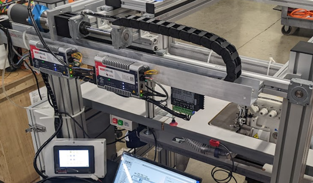
The InoWorx Motion System by Cardinal Kinetic has risen to meet this challenge — with dual 200 watt servo motors performing complex moves on an X-Y gantry, along with a Step motor to rotate the Z axis, while managing the speed of the main Sewing machine drive as well (sometimes known as a Surger).
Many of InoWorx’ key features are employed in this application, including Ethernet comms to an HMI, Ethernet sync. between servo motors, adaptive motion profiles, handling of inputs and outputs (for solenoids, cut patch delivery, etc.), and distributed mounting with visible status LEDs.
The general machine functions can be summarized as follows:
- Enable machine and home each axis to end stop
- Select either manual jog / test operation, or fully automated cycling
- Sequential moves to Pickup, Sew start point, Rotate around 4 corners, advance to cut / discharge.
- Signal cutter to deliver new patch and return to Pickup point.
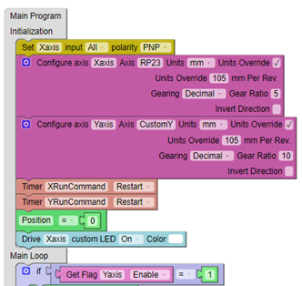
The image shows how the InoWorx programmer starts the program, with an initialization section to setup servo axes, inputs/outputs, and any other variables that only need an initial execution upon power up of the InoDrive. The bottom of the image shows the start of the “Main Loop” which marks the beginning the graphic program which loops forever - to execute all of the command entries on an on-going basis as the machine operates. The last “Get Flag” block shows one of the many ways to track progress by accessing status flags which update continuously behind the scenes.
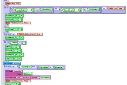
Once in the main program loop, we utilize the many functions available within InoWorx, including If / else loops which allow a multitude of checks and comparisons, One-shots to execute various operations only once, Timers, Variable assignments with intuitive naming, and much more. The blue Function Block acts much like a subroutine to execute sub groups of code and give clarity to the program.
In this case, the Blue wrapped function is named "TurnLogic" which is critical to the success of this high speed Sewing operation. The main purpose of grouping logic in this way is for the purpose of clarity, to allow the programmer to review and adjust logic which is responsible for a given task.
The blocks in Pink are responsible for setting of the Motion profiles and to issue the actual Move commands to run the motors. The “Modify” block allows us to vary the run speed of the profile, depending on which section of the patch is being sewn. In this case, the material patch is asymmetrical, so the X-Y motion is different for different corners of the patch. To create the curved moves needed for this system, we are concatenating moves together, with speed and gain modification occurring “mid-move”, a very powerful feature which is paramount to solving this application.
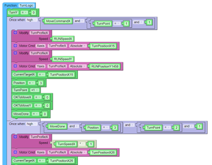
When a variety of patch sizes and shapes are to be processed on these machines, there is a need for multiple recipes and adjustable parameters to handle each product properly. The Modbus TCP interface over Ethernet gives the operator or technician direct access to the internal InoDrive parameters (variables).
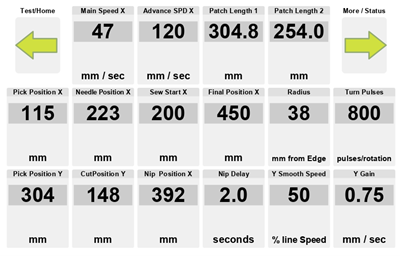
Shown above are just some of the parameters designed into this system. Each parameter represents a variable within the InoDrive, and the variable names, scaling, and units of measure are maintained for ease of understanding to the technician. Each value is able to be adjusted, is automatically saved into memory, and can be immediately invoked and tested to see the impact of the change. InoDrive is completely HMI agnostic, offering compatibility to virtually all units on the general market.
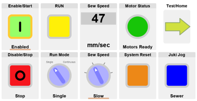
Once parameters are set within the system, one can access the main operator screen to Enable / Disable, Select Mode, Jog/Reset, Set speed, Run the system, access other screens for testing, and much more. This is just one example of the many styles of interface that can offer control and visibility into the InoDrive Motion Control system.